The Cottage of Wattage
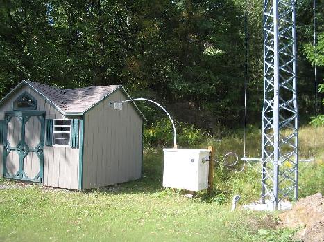
This is the K2PG AM transmitter near Shickshinny, PA. It went on the air in late February, 2007.
The Collins 21E transmitter is too large to fit into my little ranch house, so I got myself a small prefabricated shed to house it and all ancillary equipment. The antenna matching network is in the white box between the shed and the tower. The antenna is a short folded unipole on a 64 foot Rohn tower.
Many thanks to WD2AFJ (Ray), W2OBR (Rich), N3WWL (Jay), W3SLK (Mike), and their friends who helped me move the transmitter from storage in New Jersey to this shed. Thanks also to KB3MMM (Dave) and his friend, who helped me to right the very heavy transmitter cubicles inside the shed, Len Crawford for setting up my electrical service entrance, and Don and Ron Spivak for erecting the tower.
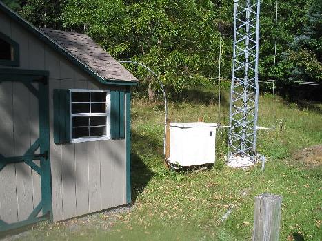
Another view of the Cottage of Wattage. The PVC conduit at the tower base contains the feedline for a 2 meter antenna, which is mounted on the top of the tower.
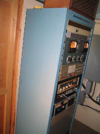
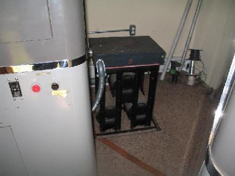
This rack contains the modulation monitor, a remote control unit allowing control of the transmitter from my living room, a Shure audio mixer, some audio processing equipment, a tape cartridge machine for test announcements and IDs, and a delay relay to protect the receiver from the slowly decaying RF from the transmitter.
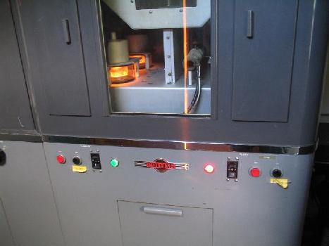
The Collins 21E transmitter, lit up and in action.
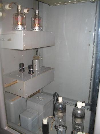
The driver section of the 21E, showing the 6SJ7 and 4-125A audio tubes, the 872A high voltage rectifiers, one of the low voltage rectifier stacks, and the 5U4GB bias rectifier.
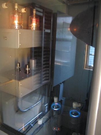
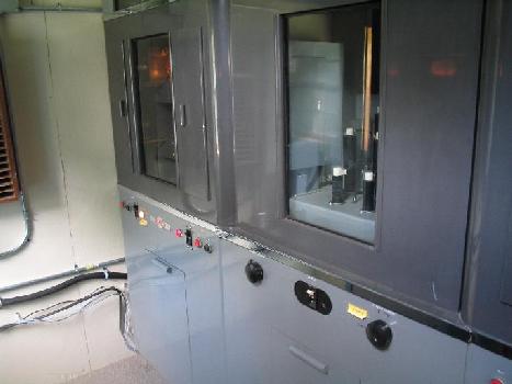
This is a better view of the lit tubes, albeit with reflections in the viewing window.
The 3X3000 modulator tubes and PA plate RF choke. The screened window covers the PA tank circuit, a Pi-L design.
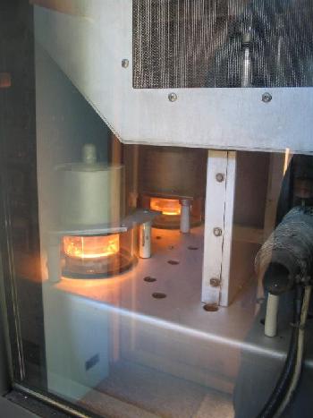
The PA cubicle, lit up and in action.
The three phase plate transformer, made by Peter Dahl. It replaced the original PCB-laden transformer. It has been "tapped down" to reduce the transmitter power.
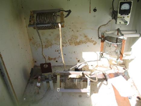
The antenna coupling unit. This is a simple T network
for matching the shortened folded unipole antenna to a 50 ohm
feedline and for tuning out the reactance inherent in such
antennas.
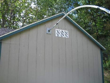
The feedline exiting the transmitter shed. This is 7/8 inch foam dielectric Heliax cable. Since I could not afford the feedline ports used in most commercial installations, I ran the feedline through a piece of sheet metal, using an automotive grommet to prevent the metal from nicking the jacket and to keep rainwater out of the shed.
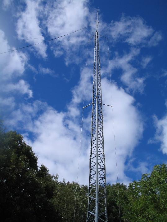
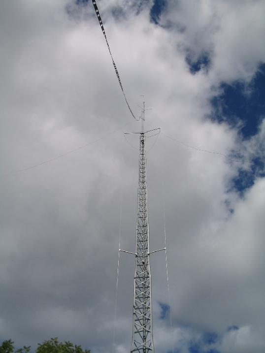
The tower, showing the folded unipole skirt, commoning ring, and a 2 meter Ringo Ranger at its top. The unipole spacers are standard PVC plumbing pipe obtained from a local building supply store. The "ladder line" feeds an inverted vee antenna for 80 meters and up.
Another view of the tower.